Testing process is important part of software development cycle. Errors in problem statement, architectural design and program code writing shall be discovered as soon as possible until they result in failure to keep within a time limit or other negative consequences.
The central problem of Automated Process Control System development in an office environment is that testing is made in absolute lack of automation objects. Furthermore, some situations could not be simulated at real object for reasons of safety, cost, etc.
One solution of the problem is the development of automated process simulator with sufficient fidelity level, so called - Factory Acceptance Test (FAT) simulator.
Three layers of architecture of the proposed simulator can be separated:

- User Interface is meant for a specialist performing the testing. This layer is aimed at simulator parameters control for simulation of various situations.
- Simulation Logic - the main layer of architecture imitating the behavior of automation objects depending on parameters set by tester, output signals of tested system and logic set in a simulator. The result of operation of this layer is displayed by user interface and is transferred to the tested system in the form of input signals.
- Communication – the layer, which is responsible for information transfer between simulator and tested system.
There are two main variants for the implementation of a lower layer of architecture: hardware simulator and software simulator.
Hardware simulator
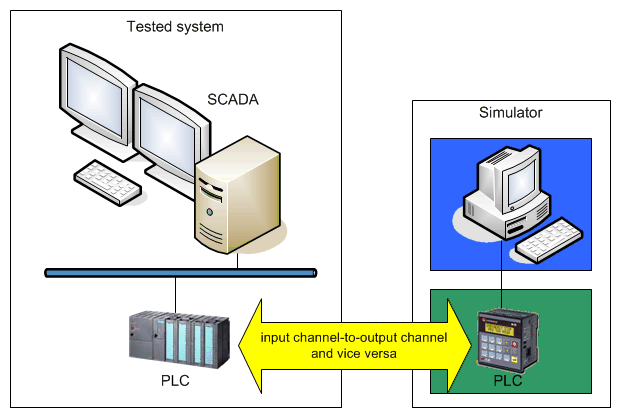
Physical channel of tested system are connected to the simulator on the principle "input channel-to-output channel”, and vice versa. As one variant for the implementation of simulation logic - PLC, and as user interface - the suitable HMI package for SCADA system, can be used.

 Advantages:
- Software and hardware part of tested system, including channels for input/output signals, are tested simultaneously.
 Disadvantages:
- Sufficient base of free hardware, which by number of signals is directly proportional to tested system dimensions, is required.
- The time for wiring of connections between the simulator and tested system should be taken into account.
It may be supposed that hardware simulator is suitable for testing small (according to the number of input/output signals) automation systems or systems consisting of small independent subsystems.
Software simulator
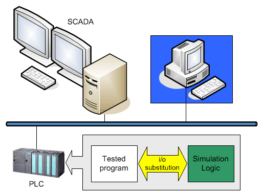
Connection of signals of tested system and simulator is carried out by software. In the simplest case the simulation logic may be implemented in PLC of tested system. During testing PLC ignores input signals from physical channels and imitates this information with the use of supplementary logic having regard to output signals of system.

 Advantages:
- Both disadvantages of hardware simulator are not observed.
 Disadvantages:
- Channels for input/output signals of system need to be tested separately.
- PLC program code is complicated - has functions unrelated to tasks of tested system and additional resources are needed (CPU, Memory).
One of the disadvantages of the approach may be partially neutralized if only the task for substitution of information is left in PLC, for example, depending upon the state of software switch. In this case the simulation logic should be implemented with the help of other means and network interface (OPC, Modbus) can be used for data communication.

«Process Simulator» - is a universal platform for rapid development of Factory Acceptance Test simulator.
Simulator may be used for debugging and testing of Automated Process Control System software, and for the training of technology operators, who will operate this system later on.
The simulator project is saved in the form of XML file allowing to edit it manually and to use template code generation and version control system.
Plug-in architecture allows unlimited extension of functionality. API is open for creating Connections with Items, Converters and Simulation objects with Panels.
